The most desired characteristic for components in vehicle-mounted use is improved performance when it comes to vibration durability. The key points of the technology to improve vibration durability are explained below.
The left side of Table 1 shows the vibration conditions in general applications where vibration is not particularly a concern. The right-hand column shows an example of vibration conditions required, for example, by manufacturers of vehicle-mounted electronic equipment. When we compare the top-level frequency range, the vibration conditions in the left-hand column for the applications where vibrations are not a particular concern has a relatively narrow range of 10 to 55 Hz. While in contrast, the vibration tests that are required, for example, by manufacturers of vehicle-mounted electronic equipment have a broad range of frequencies from 10 to 2000 Hz. This is because a variety of vibrational modes can be expected in automobiles. Meaning, products are needed that can withstand vibrations on a broader range of frequencies.
The test times for both categories are identical, two hours in each of the three axial directions.
According to Table 1 the vibration conditions that are required in aluminum electrolytic capacitors for vehicle-mounted electronic equipment are severe, both in terms of the breadth of the frequency ranges and the products that are exposed to high levels of acceleration. When the vertical-type chip aluminum electrolytic capacitors are used in vehicle-mounted equipment, it is essential to have an adequately high level of durability to vibration.
Table 1: Comparison of Vibration Test Conditions
|
JIS5102 8.2 |
Example of User Requirements |
| Frequency range |
10 to 55 Hz |
10 to 2000Hz |
| Vibrational amplitude |
1.5mm or 98 m/s2, which ever is smaller |
10G to 16G |
| Time |
Two hours in each of the three axial directions |
Two hours in each of the three axial directions |
Test searching results for the resonance conditions of a typical chip aluminum electrolytic capacitor are presented as a reference below. These results show the forces subjected to the capacitor. The test conditions were a sweep frequency range between 10 and 2000 Hz, which spanned 7.5 minutes. Graph 1 shows the test results when the vibration was applied in the direction shown in Figure 1, anticipating broken leads in the chip aluminum electrolytic capacitor as the failure mode in the vibration test.
At the low frequency range, there was no resonance and the capacitor was subjected to 1G of force. However, when the frequency was increased, the acceleration on the capacitor went up by a factor of ten due to resonance. If we treat the capacitor as a solid aluminum block, there would be no resonance at this type of low frequency. Thus it would be assumed that a characteristic vibration was stimulated in the actual capacitor. Since, the acceleration of the capacitor increased by a factor of ten at around 300 Hz given a uniform 1G applied vibration. This increase factor would imply expectations of the acceleration reaching all the way to 100G at the vicinity of 300 Hz when there is a uniform applied vibration.
At that moment, the resonant frequency and the acceleration are affected in various ways by the product's circuit board. Although generalizations were not made, the structure of the chip aluminum electrolytic capacitors is certainly not robust to the broad range of frequencies. Especially, when we consider securing the capacitor to the circuit board by the component's shaped electrode leads alone.
Figure 1
Graph 1: Vibration Durability Performance of a Typical Type of Chip Aluminum Electrolytic Capacitor
Test Conditions
Sweep frequency range: 10Hz to 2000Hz
Sweep time: 7.5 minutes
Number of sweeps: 1
The structure of the typical chip aluminum electrolytic capacitor where this type of resonance occurs is explained in more detail below.
Figure 2 is a schematic diagram showing the side view of a vertical chip aluminum electrolytic capacitor, with one half of the figure showing a cut-away view.
Figure 3 shows the chip aluminum electrolytic capacitor from the bottom surface of the terminal side.
The chip aluminum electrolytic capacitor is subjected to a press process. This would improve solderability during reflow of the component's electrode leads. By shaping and cutting the leads, the configuration would serve as the electrode leads and the attached resin plate known as the "seat." The configuration would improve the stability on the circuit board when mounting the component. Also, this would protect the component from heating during the reflow process. In this structure, there will be difficult securing adequate adhesion between the body of the capacitor and the seat.
By subjecting the capacitor to a relatively large vibration, the inadequate adhesion between the capacitor's body and the seat allows the body of the capacitor to shift back and forth by the vibration. Thus, causing problems with broken electrode leads at the root of the electrode leads, where they are subjected to the largest load.
Schematic Diagram of a Typical Vertical Chip Aluminum Electrolytic Capacitor
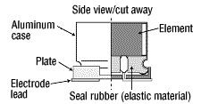
Figure 2
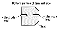
Figure 3
Countermeasures such as shown in Figure 4 are required in order to make up for this weakness and obtain a high level of vibration-resistance performance.
First, the play between the seat and the body of the capacitor must be controlled.
Even though the leads are bent so as to form an adequately tight seal between the body of the capacitor and the seat, this does not mean that the seat is affixed to the capacitor. Thus, when there is a strong vibration, the back and forth swaying of the component is unavoidable and leads to broken electrode leads.
The next key point revolves around controlling the float of the electrode leads. While the electrode leads are bent perpendicularly from the capacitor's body, it is easy to visualize a compromise of the capacitor's vibration durability. Especially, if there is a space between the electrode leads and the terminals.
The stress reduction on the terminal leads is an unavoidable and critical issue. Especially, when considering the failure mode where the electrode leads are broken at the root.
Strength improvements of the bond between the printed wiring board and the capacitor should also be considered. Such improvements are important because relative movement between the seat and the printed wiring board might break the electrode leads unless this strength is sufficient to maintain tight contact between the printed wiring board and the capacitor regardless of whether the body of the capacitor is secured to the seat.
Figure 4: Key Points in Technologies for Increasing Vibration Durability
As described above, the key to improving vibration durability revolves around reduction of the stress on the electrode lead roots.
Given this, Figure 5 shows a schematic diagram of the chip aluminum electrolytic capacitor for use in vehicle-mounted electronic equipment, as used by Elna. Figure 5-1 shows a side view of the vertical chip aluminum electrolytic capacitor for use in vehicle-mounted electronic equipment, as was shown above. Figure 5-2 is a view from the top, and
Figure 5-3 is a view from the bottom on the lead side.
The major difference between the general type of capacitor and the vibration-resistant type of capacitor is the use of adhesive resin and the in-mold supplemental terminals.
In order to obtain the tight contact between the seat and the capacitor, an adhesive resin is used to fasten the aluminum case to the seat by securing it immovably. Additionally, in order to take full advantage of the tight connection between the seat and the capacitor, the seat is equipped with two in-mold supplemental terminals. These four terminals (the electrode terminals and the supplemental terminals) should be used to ensure tight contact between the product and the printed wiring board by soldering the terminals in the reflow process. This makes it possible to secure the entire capacitor to the wiring board using the in-mold supplemental terminals. Thereby, it will reduce the stresses on the electrode terminal and improve the vibration durability.
Schematic Diagram of the Vertical Chip Aluminum Electrolytic Capacitor for Mounting in Vehicles
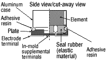
Figure 5-1
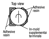
Figure 5-2
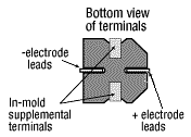
Figure 5-3
Graph 2 shows the results of vibration durability testing on the vibration-resistant vertical chip aluminum electrolytic capacitor. While testing using the same process described above, these results showed the performed countermeasures. When comparing previous results with the same test conditions and the same vibration direction, the peak acceleration displayed a drop by a factor of 2.5 and a dramatic amplitude reduction of 75% compared to the typical capacitor. This is the effect of securely fastening the body of the capacitor to the printed wiring board through the use of the in-mold supplemental terminals, and of using the adhesive resin to secure the aluminum case to the seat. The point of resonance was also shifted to higher frequencies. Also, the resonance, at approximately 300Hz had also been eliminated.
Here, the excess vibrations were suppressed through the vibration durability countermeasures performed on the chip aluminum electrolytic capacitor. These countermeasures indicate a point of resonance shift to the high frequency side.
The vibration-resistant type, wherein the level of adhesion between the capacitor as a whole and the printed wiring board, has eliminated the resonance seen in the standard capacitor. Also, this vibration-resistant standard has adequately reduced the relative movement of the capacitor.
Peak Acceleration at the Resonant Frequency (Elna Chip-type Capacitors for Use in Vehicle-mounted Electronic Equipment)
Graph 2: Vibration Durability Performance of the Elna Chip-type Capacitors for Use Vehicle-mounted Electronic Equipment
Test Conditions
Sweep frequency range: 10Hz to 2000Hz
Sweep time: 7.5 minutes
Number of sweeps: 1
This vibration-resistant capacitor uses an adhesive resin for the purpose of increasing durability from vibration. The adhesive resin has a large impact on the vibration-resistant performance. Figure 6 shows the required performance sought in the adhesive resin.
First, it is essential that there be excellent adhesion to the seat and to the aluminum case. Naturally, this requires adequate adhesion to both of these different materials.
Next there is the ability to withstand high temperatures. The resin adhesive must maintain adequate adhesive strength even when the product is exposed to high temperatures because of thermal transmission from heat sources. Especially, heat sources transmitted from automobile engines.
Even in high-humidity environments, the resin adhesive must be able to maintain adequate adhesive strength.
When considering high-volume manufacturing of electronic components, the viscosity of the resin and the length of the pot life are less critical elements.
As a result of investigating a variety of resins to fulfill these requirements, Elna now uses a polyurethane adhesive resin. Graph 3 shows the reliability of the adhesive resin.
In order to check reliability of the adhesive resin, two test pieces made from the same material were fabricated and then adhered together using the adhesive resin. After the test piece were stored under the various environmental conditions, the samples were torn apart and measured for tensile strength. The vertical axis shows the pulling strength indicating the strength relative to the initial 100%.
Even after high humidity storage at 85% and high temperature storage of 85°C and 125°C, there was very little reduction in the adhesive strength.
Next, we examined the significant degree of difference there are with the standard capacitor in vibration tests, when used in actual products.
In the vibration tests, the vibration frequencies ranged from 10 to 2000Hz with an acceleration of 16G. The sweep time was set for two hours to apply a vibration for two hours each in the X, Y, and Z directions. The results are shown in Table 2.
The results showed 18 of the 20 standard capacitor test pieces failure due to broken leads, with a failure rate of 90%. In contrast, none of the 20 vibration-resistant capacitors had broken leads, with the failure rate of 0%. The vibration-resistant types showed a huge improvement in vibration performance.
Graph 4 shows the basic electrical characteristics of the capacitors.
The rate of change in capacitance (C/C), the dielectric tangent (tan δ), nor the leakage current (L.C.) showed any significant changes from before the tests to after the tests. Additionally, there were no defects such a cracking or breaking in the electrode leads or the in-mold supplemental terminals. Therefore, the product had a confirmed high reliability level.
Figure 6: Adhesive Resin
Graph 3: Reliability of the Adhesive Resin
Table 2: The Results of Vibration Tests for the Standard Capacitor and the Capacitor for Use in Vehicle-mounted Equipment
|
Standard |
The Elna Vertical Chip for Vehicle-mounted Equipment |
| Test piece |
RV-35V220μF |
RT-35V220μF |
| Number of test pieces |
20 |
20 |
| Number of pieces with broken leads |
18/20 |
0/20 |
| Failure rate (%) |
90 |
0 |
Graph 4: Results of Vibration Tests (Electrical Characteristics)
Vibration Conditions
Frequencies: 31.6Hz to 2000Hz
Acceleration: 16G, Sweep time: 2 hours
Vibration time: 2 hours each in the X, Y, and Z directions


