Figure 1 shows the basic concepts of how capacitors function.
A dielectric material is layered between two metal electrodes, and an electrical charge proportional to the voltage is stored in the capacitor when a voltage is applied across the electrodes.
"C" is the capacitance of the capacitor. The capacitance is calculated using the equation shown below as a function of the surface area of the electrodes (S), the distance between the electrodes (t), and the dielectric constant of the dielectric (ξ).
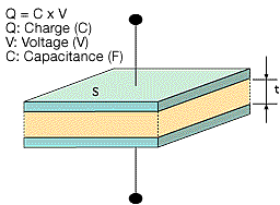
Figure 1
In the formula above, ξ0 represents the permittivity of free space (8.85 x 10⁻¹²F/m)
A larger capacitance can be obtained by either increasing the dielectric constant, increasing the electrode surface area (S), or by decreasing the distance between the electrodes (t).
The dielectric constant of an aluminum oxide layer averages between 7 and 8. The most frequent dielectric constants of dielectrics used in capacitors are listed in Table 1.
Table 1
| Dielectric Material | Dielectric Constant | Dielectric Material | Dielectric Constant |
|---|---|---|---|
| Aluminum oxide thin film | 7 - 8 | Porcelain (ceramic) | 10 - 120 |
| Mylar | 3.2 | Polyethylene | 2.5 |
| Mica | 6 - 8 | Tantalum oxide film | 10 - 20 |
The effective surface area of aluminum electrolytic capacitors can be increased by as much as 120 times. By roughening the surface of the high-purity aluminum foil, the process makes it possible to produce capacitances far larger than those of other types of capacitors.
Please note that capacitors are typically described in terms of the primary dielectric material. A few examples are "aluminum electrolytic capacitor" or "tantalum capacitor."
The anode in the aluminum electrolytic capacitor is made from a high-purity aluminum foil with an aluminum oxide thin film dielectric on its surface. The capacitor is structured using an electrolytic paper containing an electrolytic solution and an aluminum electrode foil for contacting the cathode.
The thickness of the anode oxide thin film is the distance between the electrodes (t) in Figure 2 in the section on how capacitors function. The thickness of the anode oxide thin film in an aluminum electrolytic capacitor is selected by the required withstand voltage. Large amounts of charge can be stored in a small capacitor because the value for can be made extremely small. This occurs because the value for the electrode surface area (S) can be increased by roughening the surface, and because the dielectric constant (ξ) is large.
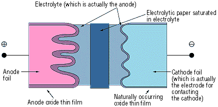
Figure 2
The raw foil for the anode uses a high-purity aluminum foil (a minimum purity level of 99.99%) that is normally 50 to 100 µm thick. The cathode foil material uses an aluminum foil that is at least 99% pure and about 15 to 60 µm thick. Because the capacitance is proportional to the surface area of the electrodes, the effective surface area is increased by roughening (etching) the surface of the aluminum foil before growing the dielectric film. Generally, this surface roughening is referred to as "etching."
There are two typical etching processes. The first option submerges the aluminum foil in hydrochloric acid (physical etching). A secondary option is electrolysis where the aluminum as the anode is placed in an aqueous hydrochloric acid solution (electrochemical etching). In electrochemical etching, the etching profile will vary depending on factors such as the waveform of the electrical current, the composition of the solution, and the temperature. The etching method can be determined by the desired capacitor performance. Generally, it is possible to achieve etching multipliers (the ratio between the surface area of the smooth foil and the effective surface area of the etched foil) approximately between 3 and 120.
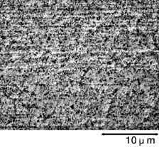
The foil is then rinsed thoroughly with water. Any residual chlorine ions on the foil's surface after etching can corrode the foil and damage the capacitor. After etching, the foil's surface can be categorized broadly as shown below by the selected voltage at which the capacitor functions properly. See the magnified view of the surface in Photograph 1.
Photograph 1: Types of Etched Foils
| Low-voltage foil | High-voltage foil | ||
|---|---|---|---|
| Foil Surface(3500× Magnification) | Cross-section of Capacitor(350× Magnification) | Foil Surface(3500× Magnification) | Cross-section of Capacitor(350× Magnification) |
 |
 |
 |
 |
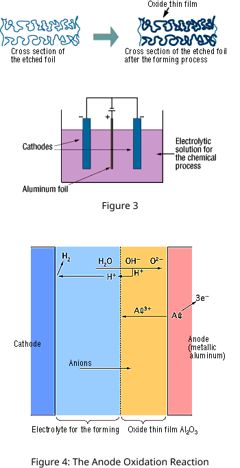
The "Forming" process is defined by creating an electrically insulating oxide (to provide the withstand voltage) on the aluminum surface by performing anode oxidation in the electrolytic solution used for the growth. The produced chemical film is used as the anode thin film.
The anode oxidation, as shown in Figure 3, is produced by applying a voltage to the submerged foil found in the electrolytic solution used for growing the oxide film. Generally, the electrolytic solution is an aqueous solution such as ammonium boric acid, ammonium phosphate, or ammonium adipic for acid.
During the anode oxidation (DC electrolysis), AL2O3 is produced by a reaction between the water and the aluminum's Al3+ ions. The thickness of the grown thin film is nearly proportional to the applied voltage] with approximately 1.0 to 1.4 nm per volt. The chemical reactions on the anode side and the cathode side are as follows.
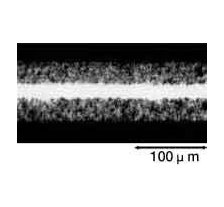
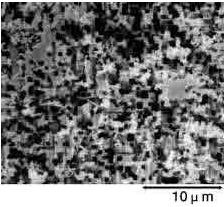
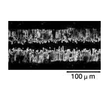
Photographs 2 and 3 show a magnified view of the oxide layer produced through anode oxidation.
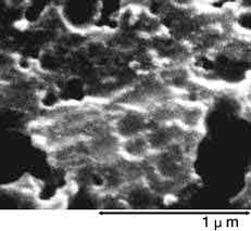
Photograph 2: Low-voltage forming foil
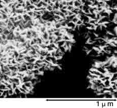
Photograph 3: High-voltage forming foil
Aluminum electrolytic capacitors are made by layering the electrolytic paper between the anode and cathode foils, and then coiling the result. The process of preparing an electrode facing the etched anode foil surface is extremely difficult. Therefore, the opposing electrode is created by filling the structure with an electrolyte. Due to this process, the electrolyte essentially functions as the cathode. The basic functional requirements for the electrolyte are as follows:
The grown oxide layer, resulting from the solute and the solvent (electrolyte), greatly controls the performance of the aluminum electrolytic capacitor. The component materials generally used are as shown in Table 2.
Table 2: An Example of the Composition of the Electrolyte
| Type | Typical Compound | Chemical Formula | Structural Formula | ||
|---|---|---|---|---|---|
| Solvent | Glycol | Ethylene glycol | C2H6O2 |  |
|
| Lactone | γ-Butyrolactone | C4H6O2 |  |
||
| Solute | Acid | Aliphatic carboxylic acid | Adipic acid | C6H10O4 |  |
| Aromatic carboxylic acid | Phthalic acid | C8H6O2 |  |
||
| Base | Ammonia | Ammonia | NH3 |  |
|
| Amine | Triethylamine | C6H15N |  |
||
| Amidine | Tetramethylimidazolinium | C7H15N2 |  |
||


